
负载均衡的园区网络综合实训
负载均衡的园区网络综合实训
任务描述
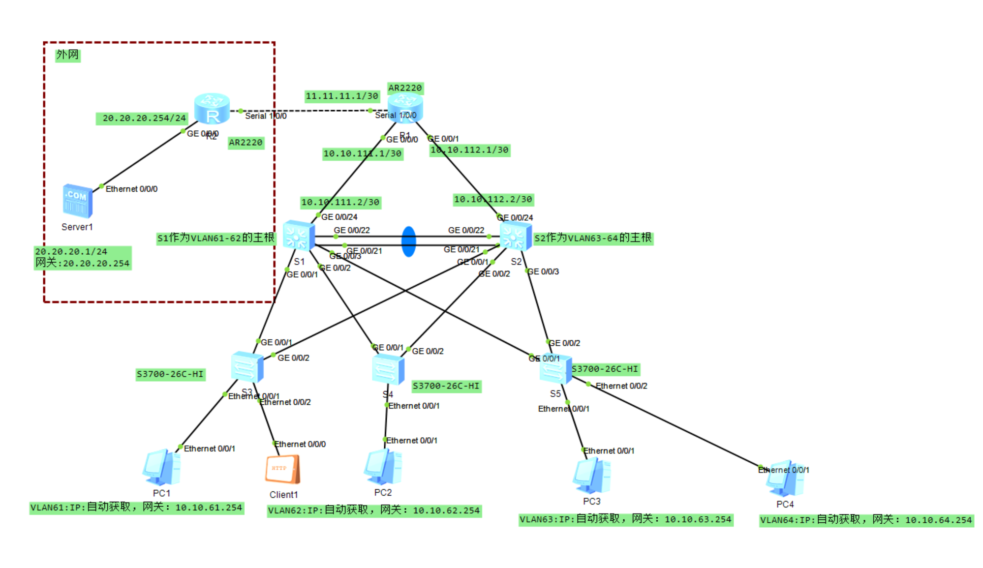
单核心的网络已经无法满足公司的需求,因此采用双核心的冗余网络,可以保证公司网络的稳定性。利用MSTP(多生成树协议)和VRRP(虚拟路由冗余协议)提高可靠性,实现冗余备份的同时,可实现负载均衡,MSTP协议中创建多个生成树实例,实现VLAN间负载均衡,不同VLAN的流量按照不同的路径转发。VRRP协议中创建多个备份组,各备份组指定不同的Master与Backup,实现虚拟路由的负载均衡。
项目要求
(1)该企业内网S1和S2核心交换机互为备份,实现链路聚合,设备冗余设计,核心交换机通过路由器R1与互联网连通。
(2)路由器R1与路由器R2通过PPP链路连接,启用PPP协议的CHAP认证功能,路由器R2为认证方,路由器R1被认证方,用户名使用路由器名称,认证加密类型密钥为:123456。
(3)路由器R1与路由器R2之间不配置路由协议,可通过默认路由配置实现网络通信。
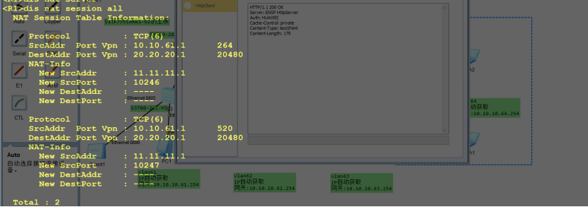
(4)路由器R1上配置NAT地址转换,使内部计算机能访问互联网服务器Server1。
(5)所有VLAN的网关在核心交换机上实现,S1和S2核心交换机与路由器R1通过OSPF实现路由互通,认证模式和秘钥采用md5 1 ciper gd。
(6)在S1和S2核心交换机上分别配置DHCP服务,实现高可用的DHCP服务器双机热备,使得客户端都可以动态获取正确的IP地址。
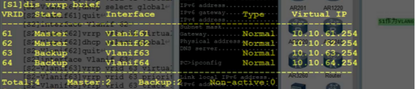
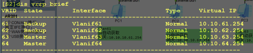
(7)在S1和S2核心交换机启用VRRP协议,并且配置使VLAN 61、VLAN 62数据流默认通过S1转发,VLAN 63、VLAN 64数据流默认通过S2转发。
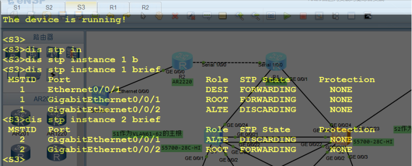
(8)整个网络启用MSTP多生成树,设置S1作为生成树实例1的根,配置VLAN 61、VLAN 62参与生成树实例1,配置S2作为生成树实例2的根,配置VLAN 63、VLAN 64参与生成树实例2。
(9)S3、S4和S5交换机作为接入层交换机,分别连接VLAN 61、VLAN 62、VLAN 63虚拟局域网。
项目实施
1.交换机的基础配置
接入层交换机S3的基本配置。
<Huawei>system-view
[Huawei]sysname S3
[S3]undo info-center enable
[S3]vlan batch 61 to 64          //批量创建VLAN61-64
[S3]interface Ethernet 0/0/1
[S3-Ethernet0/0/1]port link-type access
[S3-Ethernet0/0/1]port default vlan 61
[S3]interface Ethernet 0/0/2
[S3-Ethernet0/0/1]port link-type access
[S3-Ethernet0/0/1]port default vlan 61
[S3]port-group group-member GigabitEthernet 0/0/1 to GigabitEthernet 0/0/2
[S3-port-group]port link-type trunk
[S3-port-group]port trunk allow-pass vlan 61 to 64 //允许VLAN61-64通过
接入层交换机S4的基本配置。
<Huawei>system-view
[Huawei]sysname S4
[S4]undo info-center enable
[S4]vlan batch 61 to 64                          //批量创建VLAN61-64
[S4]interface Ethernet 0/0/1
[S4-Ethernet0/0/1]port link-type access
[S4-Ethernet0/0/1]port default vlan 62
[S4-Ethernet0/0/1]quit
[S3]port-group group-member GigabitEthernet 0/0/1 to GigabitEthernet 0/0/2
[S3-port-group]port link-type trunk
[S3-port-group]port trunk allow-pass vlan 61 to 64 //允许VLAN61-64通过
接入层交换机S5的基本配置。
<Huawei>system-view
[Huawei]sysname S5
[S5]undo info-center enable
[S5]vlan batch 61 to 64 102                          //批量创建VLAN61-64,102
[S5]interface Ethernet 0/0/1
[S5-Ethernet0/0/1]port link-type access
[S5-Ethernet0/0/1]port default vlan 63
[S5-Ethernet0/0/1]quit
[S3]port-group group-member GigabitEthernet 0/0/1 to GigabitEthernet 0/0/2
[S3-port-group]port link-type trunk
[S3-port-group]port trunk allow-pass vlan 61 to 64 //允许VLAN61-64通过
核心交换机S1的基本配置。
<Huawei>system-view
[Huawei]undo info-center enable
[Huawei]sysname S1
[S1]vlan batch 61 to 64 102 111                          //批量创建VLAN61-64,102和111
[S1]interface GigabitEthernet 0/0/24
[S1-GigabitEthernet0/0/24]port link-type access
[S1-GigabitEthernet0/0/24]port default vlan 111
[S1-GigabitEthernet0/0/24]quit
[S3]port-group group-member GigabitEthernet 0/0/1 to GigabitEthernet 0/0/3
[S3-port-group]port link-type trunk
[S3-port-group]port trunk allow-pass vlan 61 to 64 //允许VLAN61-64通过
[S1]interface Vlanif 61
[S1-Vlanif61]ip address 10.10.61.252 255.255.255.0
[S1-Vlanif61]interface Vlanif 62
[S1-Vlanif62]ip address 10.10.62.252 255.255.255.0
[S1-Vlanif62]interface Vlanif 63
[S1-Vlanif63]ip address 10.10.63.252 255.255.255.0
[S1-Vlanif63]interface Vlanif 64
[S1-Vlanif64]ip address 10.10.64.252 255.255.255.0
[S1-Vlanif64]interface Vlanif 102                          //供AP使用
[S1-Vlanif102]ip address 10.10.102.252 255.255.255.0
[S1-Vlanif102]interface Vlanif 111
[S1-Vlanif111]ip address 10.10.111.2 255.255.255.252
[S1-Vlanif111]quit
核心交换机S2的基本配置。
<Huawei>system-view
[Huawei]undo info-center enable
[Huawei]sysname S2
[S2]vlan batch 61 to 64 102 112
[S2]interface GigabitEthernet 0/0/24
[S2-GigabitEthernet0/0/24]port link-type access
[S2-GigabitEthernet0/0/24]port default vlan 112  //设置上行链路所属VLAN
[S2-GigabitEthernet0/0/24]quit
[S3]port-group group-member GigabitEthernet 0/0/1 to GigabitEthernet 0/0/3
[S3-port-group]port link-type trunk
[S3-port-group]port trunk allow-pass vlan 61 to 64 //允许VLAN61-64通过
[S2]interface Vlanif 1                         //与AC通信
[S2-Vlanif1]ip address 10.10.101.254 255.255.255.0
[S2-Vlanif1]interface Vlanif 61
[S2-Vlanif61]ip address 10.10.61.253 255.255.255.0
[S2-Vlanif61]interface Vlanif 62
[S2-Vlanif62]ip address 10.10.62.253 255.255.255.0
[S2-Vlanif62]interface Vlanif 63
[S2-Vlanif63]ip address 10.10.63.253 255.255.255.0
[S2-Vlanif63]interface Vlanif 64
[S2-Vlanif64]ip address 10.10.64.253 255.255.255.0
[S2-Vlanif64]interface Vlanif 102                          //供AP使用
[S2-Vlanif102]ip address 10.10.102.253 255.255.255.0
[S2-Vlanif102]interface Vlanif 112
[S2-Vlanif112]ip address 10.10.112.2 255.255.255.252
2.交换机的Eth-Trunk配置
核心交换机S1的Eth-Trunk配置。
[S1]interface Eth-Trunk 1
[S1-Eth-Trunk1]port link-type trunk
[S1-Eth-Trunk1]port trunk allow-pass vlan 61 to 64 102
[S1-Eth-Trunk1]quit
[S1]interface GigabitEthernet 0/0/21
[S1-GigabitEthernet0/0/21]eth-trunk 1
[S1-GigabitEthernet0/0/21]quit
[S1]interface GigabitEthernet 0/0/22
[S1-GigabitEthernet0/0/22]eth-trunk 1
核心交换机S2的Eth-Trunk配置。(方法二)
[S2]interface Eth-Trunk 1
[S2-Eth-Trunk1]trunkport GigabitEthernet 0/0/21 to 0/0/22
[S2-Eth-Trunk1]port link-type trunk
[S2-Eth-Trunk1]port trunk allow-pass vlan 61 to 64 102
3.交换机的MSTP配置
在交换机S1,S2,S3,S4,S5上执行以下命令,配置MSTP参数
stp region-configuration
 region-name test
 revision-level 1
 instance 1 vlan 61 to 62
 instance 2 vlan 63 to 64 102
 active region-configuration
核心交换机S1的MSTP配置。
[S1]stp instance 1 priority 0
[S1]stp instance 2 priority 4096
核心交换机S2的MSTP配置。
[S2]stp instance 1 priority 4096
[S2]stp instance 2 priority 0
在S3上验证MSTP
4.在交换机上配置DHCP给有线客户端使用
在核心交换机S1上的配置。
[S1]dhcp enable
[S1]ip pool vlan61
[S1-ip-pool-vlan61]network 10.10.61.0 mask 255.255.255.0
[S1-ip-pool-vlan61]excluded-ip-address 10.10.61.252 10.10.61.253
[S1-ip-pool-vlan61]gateway-list 10.10.61.254
[S1-ip-pool-vlan61]dns-list 114.114.114.114
[S1-ip-pool-vlan61]quit
[S1]ip pool vlan62
[S1-ip-pool-vlan62]network 10.10.62.0 mask 255.255.255.0
[S1-ip-pool-vlan62]excluded-ip-address 10.10.62.252 10.10.62.253
[S1-ip-pool-vlan62]gateway-list 10.10.62.254
[S1-ip-pool-vlan62]dns-list 114.114.114.114
[S1-ip-pool-vlan62]quit
[S1]ip pool vlan63
[S1-ip-pool-vlan63]network 10.10.63.0 mask 255.255.255.0
[S1-ip-pool-vlan63]excluded-ip-address 10.10.63.252 10.10.63.253
[S1-ip-pool-vlan63]gateway-list 10.10.63.254
[S1-ip-pool-vlan63]dns-list 114.114.114.114
在核心交换机S2上的配置。
[S2]dhcp enable
[S2]ip pool vlan61
[S2-ip-pool-vlan61]network 10.10.61.0 mask 255.255.255.0
[S2-ip-pool-vlan61]excluded-ip-address 10.10.61.252 10.10.61.253
[S2-ip-pool-vlan61]gateway-list 10.10.61.254
[S2-ip-pool-vlan61]dns-list 114.114.114.114
[S2-ip-pool-vlan61]quit
[S2]ip pool vlan62
[S2-ip-pool-vlan62]network 10.10.62.0 mask 255.255.255.0
[S2-ip-pool-vlan62]excluded-ip-address 10.10.62.252 10.10.62.253
[S2-ip-pool-vlan62]gateway-list 10.10.62.254
[S2-ip-pool-vlan62]dns-list 114.114.114.114
[S2-ip-pool-vlan62]quit
[S2]ip pool vlan63
[S2-ip-pool-vlan63]network 10.10.63.0 mask 255.255.255.0
[S2-ip-pool-vlan63]excluded-ip-address 10.10.63.252 10.10.63.253
[S2-ip-pool-vlan63]gateway-list 10.10.63.254
[S2-ip-pool-vlan63]dns-list 114.114.114.114
5.交换机的VRRP配置
核心交换机S1的VRRP配置。
[S1]dhcp enable
[S1]interface Vlanif 61
[S1-Vlanif61]vrrp vrid 61 virtual-ip 10.10.61.254  //设置VLAN61的虚拟网关
[S1-Vlanif61]vrrp vrid 61 priority 120            //配置vrrp组61的优先级为120
[S1-Vlanif61]vrrp vrid 61 track interface GigabitEthernet0/0/24 reduced 30
               //配置vrrp组61的检查项track端口并设置出现端口故障时优先级减少30
[S1-Vlanif61]dhcp select global                  //配置DHCP全局模式
[S1-Vlanif61]quit
[S1]interface Vlanif 62
[S1-Vlanif62]vrrp vrid 62 virtual-ip 10.10.62.254  //设置VLAN62的虚拟网关
[S1-Vlanif62]vrrp vrid 62 priority 120            //配置vrrp组62的优先级为120
[S1-Vlanif62]vrrp vrid 62 track interface GigabitEthernet0/0/24 reduced 30
               //配置vrrp组62的检查项track端口并设置出现端口故障时优先级减少30
[S1-Vlanif62]dhcp select global                  //配置DHCP全局模式
[S1-Vlanif62]quit
[S1]interface Vlanif 63
[S1-Vlanif63]vrrp vrid 63 virtual-ip 10.10.63.254
[S1-Vlanif63]quit
[S1]interface Vlanif 64
[S1-Vlanif64]vrrp vrid 64 virtual-ip 10.10.64.254
核心交换机S2的VRRP配置。
[S2]interface Vlanif 61
[S2-Vlanif61]vrrp vrid 61 virtual-ip 10.10.61.254
[S2-Vlanif61]dhcp select global
[S2-Vlanif61]quit
[S2]interface Vlanif 62
[S2-Vlanif62]vrrp vrid 62 virtual-ip 10.10.62.254
[S2-Vlanif62]dhcp select global
[S2-Vlanif62]quit
[S2]interface Vlanif 63
[S2-Vlanif63]vrrp vrid 63 virtual-ip 10.10.63.254
[S2-Vlanif63]vrrp vrid 63 priority 120
[S2-Vlanif63]vrrp vrid 63 track interface GigabitEthernet0/0/24 reduced 30
[S2-Vlanif63]dhcp select global
[S2-Vlanif63]quit
[S2]interface Vlanif 64
[S2-Vlanif64]vrrp vrid 64 virtual-ip 10.10.64.254
[S2-Vlanif64]vrrp vrid 64 priority 120
[S2-Vlanif64]vrrp vrid 64 track interface GigabitEthernet0/0/24 reduced 30
验证VRRP主从设备
6.交换机的路由配置
核心交换机S1的路由配置。
[S1]ospf 1
[S1-ospf-1]area 0
[S1-ospf-1-area-0.0.0.0]authentication-mode md5 1 cipher gd  //设置ospf验证算法为md5 密码为gd
[S1-ospf-1-area-0.0.0.0]network 10.10.111.0 0.0.0.3
[S1-ospf-1-area-0.0.0.0]network 10.10.61.0 0.0.0.255
[S1-ospf-1-area-0.0.0.0]network 10.10.62.0 0.0.0.255
[S1-ospf-1-area-0.0.0.0]network 10.10.63.0 0.0.0.255
[S1-ospf-1-area-0.0.0.0]network 10.10.64.0 0.0.0.255
[S1-ospf-1-area-0.0.0.0]network 10.10.102.0 0.0.0.255
核心交换机S2的路由配置。
[S2]ospf 1
[S2-ospf-1]area 0
[S2-ospf-1-area-0.0.0.0]authentication-mode md5 1 cipher gd
[S2-ospf-1-area-0.0.0.0]network 10.10.112.0 0.0.0.3
[S2-ospf-1-area-0.0.0.0]network 10.10.61.0 0.0.0.255
[S2-ospf-1-area-0.0.0.0]network 10.10.62.0 0.0.0.255
[S2-ospf-1-area-0.0.0.0]network 10.10.63.0 0.0.0.255
[S2-ospf-1-area-0.0.0.0]network 10.10.64.0 0.0.0.255
[S2-ospf-1-area-0.0.0.0]network 10.10.102.0 0.0.0.255
7.路由器的基本配置
路由器R1的配置。
<Huawei>system-view
[Huawei]sysname R1
[R1]undo info-center enable
[R1]interface GigabitEthernet 0/0/0
[R1-GigabitEthernet0/0/0]ip address 10.10.111.1 255.255.255.252
[R1-GigabitEthernet0/0/0]quit
[R1]interface GigabitEthernet 0/0/1
[R1-GigabitEthernet0/0/1]ip address 10.10.112.1 255.255.255.252
[R1-GigabitEthernet0/0/1]quit
[R1]interface Serial 1/0/0
[R1-Serial1/0/0]ip address 11.11.11.1 255.255.255.252
路由器R2的配置。
<Huawei>system-view
[Huawei]sysname R2
[R2]undo info-center enable
[R2]interface Serial 1/0/0
[R2-Serial1/0/0]ip address 11.11.11.2 255.255.255.252
[R2-Serial1/0/0]quit
[R2]interface GigabitEthernet 0/0/0
[R2-GigabitEthernet0/0/0]ip address 20.20.20.254 24
8.路由器的PPP配置
路由器R1的PPP配置(PPP被认证方)。
[R1]interface Serial 1/0/0
[R1-Serial1/0/0]ppp chap user R1  //配置认证账号为R1
[R1-Serial1/0/0]ppp chap password cipher 123456  //配置认证账号密码为123456
路由器R2的配置(PPP认证方)。
[R2]interface Serial 1/0/0
[R2-Serial1/0/0]ppp authentication-mode chap  //设置ppp的认证模式为CHAP
[R2-Serial1/0/0]quit
[R2]aaa
[R2-aaa]local-user R1 password cipher 123456  //添加PPP认证账号和密码
[R2-aaa]local-user R1 service-type ppp        //账号R1的服务类型为PPP
9.路由器的路由和NAT配置
[R1]ip route-static 0.0.0.0 0.0.0.0 Serial 1/0/0  //配置默认路由指向出口
[R1]ospf 1
[R1-ospf-1]area 0
[R1-ospf-1-area-0.0.0.0]authentication-mode md5 1 cipher gd
[R1-ospf-1-area-0.0.0.0]network 10.10.111.0 0.0.0.3  //配置内网互联网段
[R1-ospf-1-area-0.0.0.0]network 10.10.112.0 0.0.0.3  //配置内网互联网段
[R1-ospf-1-area-0.0.0.0]quit
[R1-ospf-1]default-route-advertise always  //宣告缺省路由
[R1-ospf-1]quit
[R1]acl 2000
[R1-acl-basic-2000]rule permit source 10.10.0.0 0.0.255.255  //配置进行NAT转换的ACL
[R1-acl-basic-2000]quit
[R1]interface Serial 1/0/0
[R1-Serial1/0/0]nat outbound 2000
项目验证
PC机能够自动获取到IP地址,网关以及DNS
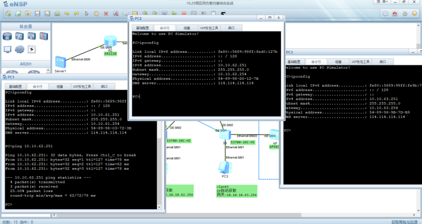
客户端能够访问服务器
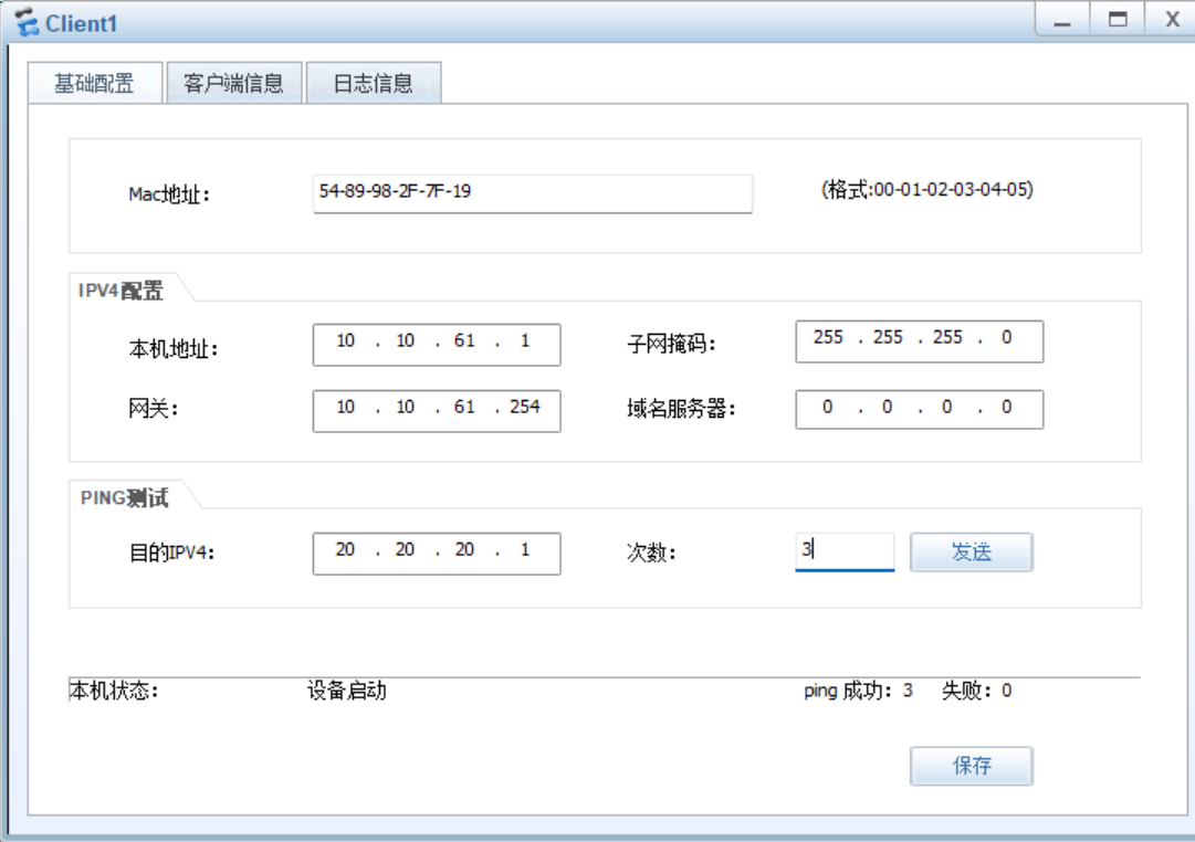
客户端配置
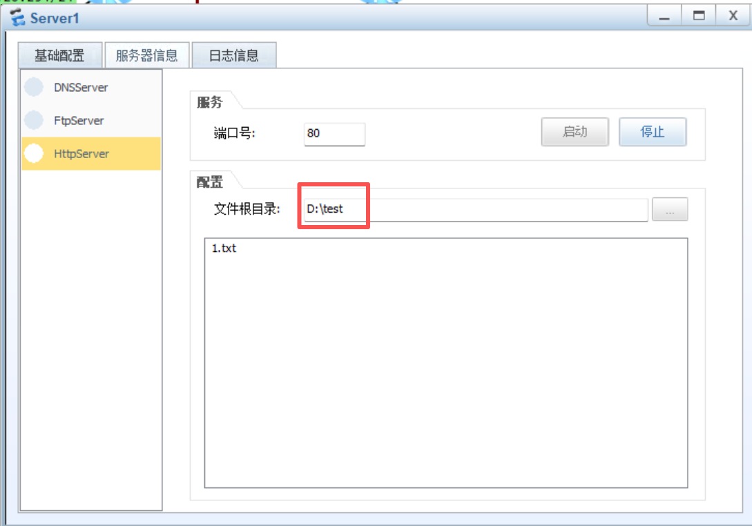
服务器配置
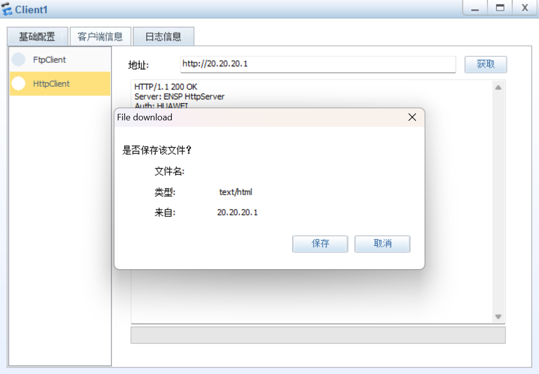
客户端访问HTTP服务器
R1上nat映射表
更多推荐


 38
38 0
0- 0


 已为社区贡献1条内容

所有评论(0)