
[极核教学]esp32IDF板载ws2812从点亮到使用,附带由例程封装的完整代码
3.1ws2812从点亮到封装成自己的文件
前言
esp32s3_devkit开发板上有一颗ws2812,而没有可以控制的常规LED,为了方便我们后续开发过程中观察现象,点亮这颗ws2812是必要的。幸运的是对于esp32来说点亮ws2812是很简单的,有很多种实现方式,不仅有两份官方例程直接修改引脚就能点亮,还有用组件也可以点亮。我们这期将通过例程来使用ws2812,下期讲组件的时候再讲如何使用组件来使用ws2812
准备
1、一块esp32s3N16R8_devkit开发板
2、一条ws2812灯带(可选)
ws2812简介
1、工作原理
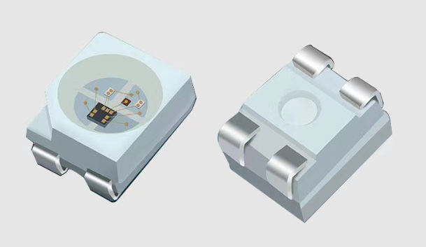
每颗ws2812除了三原色LED外还有一颗控制3个LED亮度的主控芯片,主控芯片+LED*3=ws2812。
主控芯片产生3路PWM分别控制3个灯珠,占空比通过内部锁存器来调整。比如第一个锁存器控制G,那么输入0就是设置占空比为0,输入255就是设置占空比为100,此时绿色灯珠最亮,输入128就是设置占空比为50,此时绿灯珠半亮。其他两个灯珠也是这样控制。
通过三个字节来分别设置3个灯珠的亮度从而控制ws2812整体呈现出的色彩。
2、通信原理
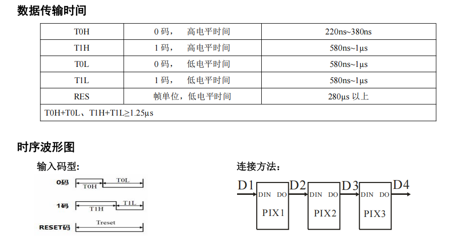
单总线通信。ws2812通过识别数据输入脚的特定波形识别数据。对它来说静默电平是常低
0码 -> 300ns高+900ns低
1码 -> 900ns高+300ns低
所以往ws2812写一个字节的数据0xFE的波形是(900ns高+300ns低)*7+(300ns高+900ns低)*1
连续写入3个字节数据那么ws2812就点亮了
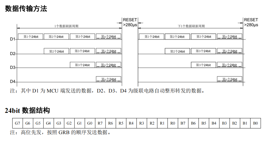
级联方式。
如果连续写入6个字节数据,比如0xDEADBEEFAABB,那么灯带上的第一颗ws2812会读取到0xDEADBE来点亮灯珠,剩下的0xEFAABB会从该ws2812的输出脚输出到灯带上的下一个灯珠,即第二颗灯珠会从第一颗灯珠的输出脚读到0xEFAABB从而点亮灯带上的第二颗ws2812灯珠。以此类推
需要了解的知识->RMT外设
时序那么复杂,我们不可能自己来翻转gpio来产生这些时序,我们需要借助esp32的外设——红外遥控 (RMT) 。
简单说rmt就是预设好0码和1码的时序,我们直接输入数组,外设自动将数组内数据按照预设的时序0101地往外丢,详细内容参考https://docs.espressif.com/projects/esp-idf/zh_CN/v5.5.1/esp32s3/api-reference/peripherals/rmt.html
跑通官方例程
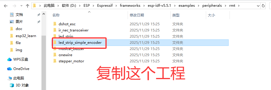
1、将Espressif\frameworks\esp-idf-v5.5.1\examples\peripherals\rmt下的led_strip_simple_encoder工程复制出来
2、修改ws2812驱动引脚(我的板子是io48)
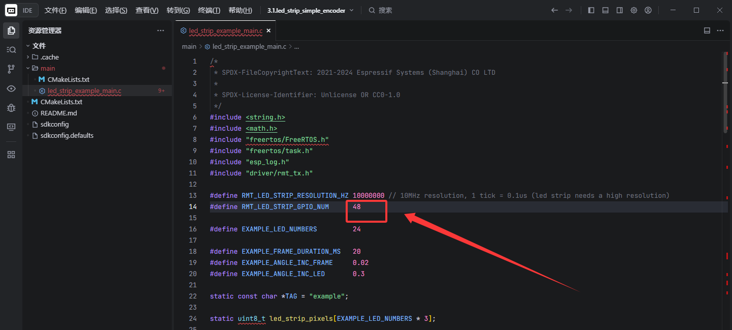
3、加载环境,完了以后设置,配置,编译烧录三部曲
idf.py set-target esp32s3
idf.py menuconfig (Flash->QIO,80Mhz,16M;PSRAM->Octal,80Mhz;主频->240Mhz)
idf.py build flash
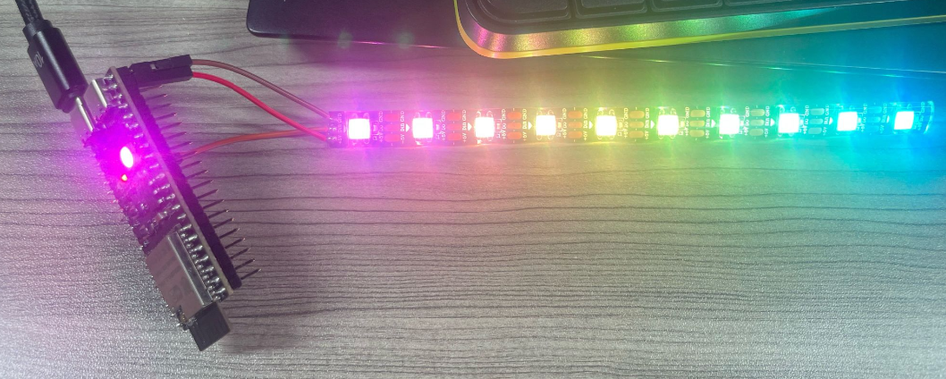
烧录完就可以看到ws2812点亮了并且在变化颜色,如果有灯带的话将数据输入脚接到io48就可以看到彩虹流光效果(注意有些开发板的5v输出是要短接板子上的IN-OUT焊盘才可以有电,至少我的板子是这样,一开始接上不亮,万用表一量是5v没电)
将例程功能封装为函数
我将例程封装成了3个函数
void ws2812_init(void) -> 无需多言
void ws2812_write_rainbow() -> 彩虹流光(调用一次变化一次灯带颜色,调用的越快则变化得越快)
void ws2812_write_GRB(uint8_t g, uint8_t r, uint8_t b) -> 将灯带中的所有颜色设置成输入的参数(GRB三原色参数)
灯珠数量,彩虹流光的参数啥的在宏定义可以修改,具体需要理解代码。这里就不解读代码了,主要是要用起来
main.c完整代码:
/*
* SPDX-FileCopyrightText: 2021-2024 Espressif Systems (Shanghai) CO LTD
*
* SPDX-License-Identifier: Unlicense OR CC0-1.0
*/
#include <stdint.h>
#include <string.h>
#include <math.h>
#include "freertos/FreeRTOS.h"
#include "freertos/task.h"
#include "esp_log.h"
#include "driver/rmt_tx.h"
#define RMT_LED_STRIP_RESOLUTION_HZ 10000000 // 10MHz resolution, 1 tick = 0.1us (led strip needs a high resolution)
#define RMT_LED_STRIP_GPIO_NUM 48
#define EXAMPLE_LED_NUMBERS 1
#define EXAMPLE_FRAME_DURATION_MS 20
#define EXAMPLE_ANGLE_INC_FRAME 0.02
#define EXAMPLE_ANGLE_INC_LED 0.3
static const char *TAG = "example";
static uint8_t led_strip_pixels[EXAMPLE_LED_NUMBERS * 3];
static const rmt_symbol_word_t ws2812_zero = {
.level0 = 1,
.duration0 = 0.3 * RMT_LED_STRIP_RESOLUTION_HZ / 1000000, // T0H=0.3us
.level1 = 0,
.duration1 = 0.9 * RMT_LED_STRIP_RESOLUTION_HZ / 1000000, // T0L=0.9us
};
static const rmt_symbol_word_t ws2812_one = {
.level0 = 1,
.duration0 = 0.9 * RMT_LED_STRIP_RESOLUTION_HZ / 1000000, // T1H=0.9us
.level1 = 0,
.duration1 = 0.3 * RMT_LED_STRIP_RESOLUTION_HZ / 1000000, // T1L=0.3us
};
//reset defaults to 50uS
static const rmt_symbol_word_t ws2812_reset = {
.level0 = 0,
.duration0 = RMT_LED_STRIP_RESOLUTION_HZ / 1000000 * 50 / 2,
.level1 = 0,
.duration1 = RMT_LED_STRIP_RESOLUTION_HZ / 1000000 * 50 / 2,
};
rmt_channel_handle_t led_chan = NULL;
rmt_encoder_handle_t simple_encoder = NULL;
rmt_transmit_config_t tx_config = {
.loop_count = 0, // no transfer loop
};
float offset = 0;
static size_t encoder_callback(const void *data, size_t data_size,
size_t symbols_written, size_t symbols_free,
rmt_symbol_word_t *symbols, bool *done, void *arg)
{
// We need a minimum of 8 symbol spaces to encode a byte. We only
// need one to encode a reset, but it's simpler to simply demand that
// there are 8 symbol spaces free to write anything.
if (symbols_free < 8) {
return 0;
}
// We can calculate where in the data we are from the symbol pos.
// Alternatively, we could use some counter referenced by the arg
// parameter to keep track of this.
size_t data_pos = symbols_written / 8;
uint8_t *data_bytes = (uint8_t*)data;
if (data_pos < data_size) {
// Encode a byte
size_t symbol_pos = 0;
for (int bitmask = 0x80; bitmask != 0; bitmask >>= 1) {
if (data_bytes[data_pos]&bitmask) {
symbols[symbol_pos++] = ws2812_one;
} else {
symbols[symbol_pos++] = ws2812_zero;
}
}
// We're done; we should have written 8 symbols.
return symbol_pos;
} else {
//All bytes already are encoded.
//Encode the reset, and we're done.
symbols[0] = ws2812_reset;
*done = 1; //Indicate end of the transaction.
return 1; //we only wrote one symbol
}
}
void ws2812_init(void)
{
ESP_LOGI(TAG, "Create RMT TX channel");
rmt_tx_channel_config_t tx_chan_config = {
.clk_src = RMT_CLK_SRC_DEFAULT, // select source clock
.gpio_num = RMT_LED_STRIP_GPIO_NUM,
.mem_block_symbols = 64, // increase the block size can make the LED less flickering
.resolution_hz = RMT_LED_STRIP_RESOLUTION_HZ,
.trans_queue_depth = 4, // set the number of transactions that can be pending in the background
};
ESP_ERROR_CHECK(rmt_new_tx_channel(&tx_chan_config, &led_chan));
ESP_LOGI(TAG, "Create simple callback-based encoder");
const rmt_simple_encoder_config_t simple_encoder_cfg = {
.callback = encoder_callback
//Note we don't set min_chunk_size here as the default of 64 is good enough.
};
ESP_ERROR_CHECK(rmt_new_simple_encoder(&simple_encoder_cfg, &simple_encoder));
ESP_LOGI(TAG, "Enable RMT TX channel");
ESP_ERROR_CHECK(rmt_enable(led_chan));
ESP_LOGI(TAG, "Start LED rainbow chase");
}
//建议20ms调用一次
void ws2812_write_rainbow()
{
for (int led = 0; led < EXAMPLE_LED_NUMBERS; led++) {
// Build RGB pixels. Each color is an offset sine, which gives a
// hue-like effect.
float angle = offset + (led * EXAMPLE_ANGLE_INC_LED);
const float color_off = (M_PI * 2) / 3;
led_strip_pixels[led * 3 + 0] = sin(angle + color_off * 0) * 127 + 128;
led_strip_pixels[led * 3 + 1] = sin(angle + color_off * 1) * 127 + 128;
led_strip_pixels[led * 3 + 2] = sin(angle + color_off * 2) * 117 + 128;
}
// Flush RGB values to LEDs
ESP_ERROR_CHECK(rmt_transmit(led_chan, simple_encoder, led_strip_pixels, sizeof(led_strip_pixels), &tx_config));
ESP_ERROR_CHECK(rmt_tx_wait_all_done(led_chan, portMAX_DELAY));
// vTaskDelay(pdMS_TO_TICKS(EXAMPLE_FRAME_DURATION_MS)); //不能在此延时
//Increase offset to shift pattern
offset += EXAMPLE_ANGLE_INC_FRAME;
if (offset > 2 * M_PI) {
offset -= 2 * M_PI;
}
}
void ws2812_write_GRB(uint8_t g, uint8_t r, uint8_t b)
{
for (int led = 0; led < EXAMPLE_LED_NUMBERS; led++) {
// Build RGB pixels. Each color is an offset sine, which gives a
// hue-like effect.
float angle = offset + (led * EXAMPLE_ANGLE_INC_LED);
const float color_off = (M_PI * 2) / 3;
led_strip_pixels[led * 3 + 0] = g;
led_strip_pixels[led * 3 + 1] = r;
led_strip_pixels[led * 3 + 2] = b;
}
// Flush RGB values to LEDs
ESP_ERROR_CHECK(rmt_transmit(led_chan, simple_encoder, led_strip_pixels, sizeof(led_strip_pixels), &tx_config));
ESP_ERROR_CHECK(rmt_tx_wait_all_done(led_chan, portMAX_DELAY));
// vTaskDelay(pdMS_TO_TICKS(EXAMPLE_FRAME_DURATION_MS)); //不能在此延时
//Increase offset to shift pattern
offset += EXAMPLE_ANGLE_INC_FRAME;
if (offset > 2 * M_PI) {
offset -= 2 * M_PI;
}
}
void app_main(void)
{
ws2812_init();
ws2812_write_GRB(0, 255, 0);
vTaskDelay(pdMS_TO_TICKS(1000*3));
while (1) {
ws2812_write_rainbow();
vTaskDelay(pdMS_TO_TICKS(EXAMPLE_FRAME_DURATION_MS));
}
}
代码现象:板载ws2812上电亮红灯3s,然后开始不断变化颜色
封装到文件
我觉得有上面的完整代码后这部分工作各位攻城狮应该可以自己完成了,想看这部分内容的我会放在视频教程里,到时候直接看视频就好了。这里我直接放文件吧,文件名叫hdw_ws2812.c和hdw_ws2812.h
头文件hdw_ws2812.h
#ifndef _HDW_WS2812_H_ #define _HDW_WS2812_H_ /*==============================================* * 包含的头文件 *----------------------------------------------*/ #include <stdint.h> #include <string.h> #include <math.h> #include "freertos/FreeRTOS.h" #include "freertos/task.h" #include "esp_log.h" #include "driver/rmt_tx.h" /*==============================================* * 宏定义/常量/typedef/enum *----------------------------------------------*/ #define RMT_LED_STRIP_RESOLUTION_HZ 10000000 // 10MHz resolution, 1 tick = 0.1us (led strip needs a high resolution) #define RMT_LED_STRIP_GPIO_NUM 48 #define EXAMPLE_LED_NUMBERS 1 #define EXAMPLE_FRAME_DURATION_MS 20 //彩虹灯条刷新时间,当前未使用 #define EXAMPLE_ANGLE_INC_FRAME 1 //越大则每次调用rainbow时LED颜色变化越明显 #define EXAMPLE_ANGLE_INC_LED 0.3 //越大则调用rainbow时整条灯带每个灯珠的颜色差异越明显 /*==============================================* * 全局变量 *----------------------------------------------*/ /*==============================================* * 函数实现 *----------------------------------------------*/ void ws2812_init(void); void ws2812_write_rainbow(void); void ws2812_write_GRB(uint8_t g, uint8_t r, uint8_t b); void ws2812_on(void); void ws2812_off(void); #endif /* _HDW_WS2812_H_ */
源文件hdw_ws2812.c
/*==============================================*
* 包含的头文件
*----------------------------------------------*/
#include "hdw_ws2812.h"
/*==============================================*
* 宏定义/常量/typedef/enum
*----------------------------------------------*/
/*==============================================*
* 全局变量
*----------------------------------------------*/
static const char *TAG = "ws2812";
static uint8_t led_strip_pixels[EXAMPLE_LED_NUMBERS * 3];
static const rmt_symbol_word_t ws2812_zero = {
.level0 = 1,
.duration0 = 0.3 * RMT_LED_STRIP_RESOLUTION_HZ / 1000000, // T0H=0.3us
.level1 = 0,
.duration1 = 0.9 * RMT_LED_STRIP_RESOLUTION_HZ / 1000000, // T0L=0.9us
};
static const rmt_symbol_word_t ws2812_one = {
.level0 = 1,
.duration0 = 0.9 * RMT_LED_STRIP_RESOLUTION_HZ / 1000000, // T1H=0.9us
.level1 = 0,
.duration1 = 0.3 * RMT_LED_STRIP_RESOLUTION_HZ / 1000000, // T1L=0.3us
};
//reset defaults to 50uS
static const rmt_symbol_word_t ws2812_reset = {
.level0 = 0,
.duration0 = RMT_LED_STRIP_RESOLUTION_HZ / 1000000 * 50 / 2,
.level1 = 0,
.duration1 = RMT_LED_STRIP_RESOLUTION_HZ / 1000000 * 50 / 2,
};
rmt_channel_handle_t led_chan = NULL;
rmt_encoder_handle_t simple_encoder = NULL;
rmt_transmit_config_t tx_config = {
.loop_count = 0, // no transfer loop
};
float offset = 0;
/*==============================================*
* 函数实现
*----------------------------------------------*/
static size_t encoder_callback(const void *data, size_t data_size,
size_t symbols_written, size_t symbols_free,
rmt_symbol_word_t *symbols, bool *done, void *arg)
{
// We need a minimum of 8 symbol spaces to encode a byte. We only
// need one to encode a reset, but it's simpler to simply demand that
// there are 8 symbol spaces free to write anything.
if (symbols_free < 8) {
return 0;
}
// We can calculate where in the data we are from the symbol pos.
// Alternatively, we could use some counter referenced by the arg
// parameter to keep track of this.
size_t data_pos = symbols_written / 8;
uint8_t *data_bytes = (uint8_t*)data;
if (data_pos < data_size) {
// Encode a byte
size_t symbol_pos = 0;
for (int bitmask = 0x80; bitmask != 0; bitmask >>= 1) {
if (data_bytes[data_pos]&bitmask) {
symbols[symbol_pos++] = ws2812_one;
} else {
symbols[symbol_pos++] = ws2812_zero;
}
}
// We're done; we should have written 8 symbols.
return symbol_pos;
} else {
//All bytes already are encoded.
//Encode the reset, and we're done.
symbols[0] = ws2812_reset;
*done = 1; //Indicate end of the transaction.
return 1; //we only wrote one symbol
}
}
void ws2812_init(void)
{
ESP_LOGI(TAG, "Create RMT TX channel");
rmt_tx_channel_config_t tx_chan_config = {
.clk_src = RMT_CLK_SRC_DEFAULT, // select source clock
.gpio_num = RMT_LED_STRIP_GPIO_NUM,
.mem_block_symbols = 64, // increase the block size can make the LED less flickering
.resolution_hz = RMT_LED_STRIP_RESOLUTION_HZ,
.trans_queue_depth = 4, // set the number of transactions that can be pending in the background
};
ESP_ERROR_CHECK(rmt_new_tx_channel(&tx_chan_config, &led_chan));
ESP_LOGI(TAG, "Create simple callback-based encoder");
const rmt_simple_encoder_config_t simple_encoder_cfg = {
.callback = encoder_callback
//Note we don't set min_chunk_size here as the default of 64 is good enough.
};
ESP_ERROR_CHECK(rmt_new_simple_encoder(&simple_encoder_cfg, &simple_encoder));
ESP_LOGI(TAG, "Enable RMT TX channel");
ESP_ERROR_CHECK(rmt_enable(led_chan));
}
//建议20ms调用一次
void ws2812_write_rainbow()
{
for (int led = 0; led < EXAMPLE_LED_NUMBERS; led++) {
// Build RGB pixels. Each color is an offset sine, which gives a
// hue-like effect.
float angle = offset + (led * EXAMPLE_ANGLE_INC_LED);
const float color_off = (M_PI * 2) / 3;
led_strip_pixels[led * 3 + 0] = sin(angle + color_off * 0) * 2 + 1;//127+128
led_strip_pixels[led * 3 + 1] = sin(angle + color_off * 1) * 2 + 1;//127+128
led_strip_pixels[led * 3 + 2] = sin(angle + color_off * 2) * 1 + 1;//117+128
}
// Flush RGB values to LEDs
ESP_ERROR_CHECK(rmt_transmit(led_chan, simple_encoder, led_strip_pixels, sizeof(led_strip_pixels), &tx_config));
ESP_ERROR_CHECK(rmt_tx_wait_all_done(led_chan, portMAX_DELAY));
// vTaskDelay(pdMS_TO_TICKS(EXAMPLE_FRAME_DURATION_MS)); //不能在此延时
//Increase offset to shift pattern
offset += EXAMPLE_ANGLE_INC_FRAME;
if (offset > 2 * M_PI) {
offset -= 2 * M_PI;
}
}
void ws2812_write_GRB(uint8_t g, uint8_t r, uint8_t b)
{
for (int led = 0; led < EXAMPLE_LED_NUMBERS; led++) {
led_strip_pixels[led * 3 + 0] = g;
led_strip_pixels[led * 3 + 1] = r;
led_strip_pixels[led * 3 + 2] = b;
}
// Flush RGB values to LEDs
ESP_ERROR_CHECK(rmt_transmit(led_chan, simple_encoder, led_strip_pixels, sizeof(led_strip_pixels), &tx_config));
ESP_ERROR_CHECK(rmt_tx_wait_all_done(led_chan, portMAX_DELAY));
}
void ws2812_on(void)
{
ws2812_write_GRB(3, 18, 12); //骚粉色
}
void ws2812_off(void)
{
ws2812_write_GRB(0, 0, 0);
}
这期没有那么详细的操作流程,默认大家都是有点基础的人了,所以直接贴代码随取随用,如果需要基本的编译烧录,移植代码啥的指导请看我前几期教程。另外代码理解靠个人,不想努力的靠ai,我就不在图文教程里教代码逻辑了,代码解读我会放在视频里
结束!喜欢就嗷两声
更多推荐



 17
17 0
0- 0


 已为社区贡献1条内容

所有评论(0)